G6ii / 19A02: Components required to measure blood pressure from an intra-arterial catheter
19A02: Exam Report
Outline the components required to measure blood pressure from an intra-arterial catheter (75% of marks). What information (other than blood pressure) may be gained from an arterial line trace (25% of marks)?
44% of candidates passed this question.
Most of the marks were allocated to the components of the measuring system (as detailed in the question), hence a level of detail was required. An explanation of how the various components work was required; e.g. hydraulic coupling and transducers. Some candidates forgot to include heart rate as a piece of information derived from the trace.
G6ii / 19A02: Components required to measure blood pressure from an intra-arterial catheter
IABP is the gold standard of BP measurement
Equipment
Intra-arterial cannula
- Short, narrow, stiff so its resident frequency is outside harmonic range
- Teflon to ↓thrombus formation
- Narrow (20 – 22G) = risk of thrombus proportional to diameter
Fluid-filled tubing
- Column of non-compressible fluid for Hydraulic Coupling
- Short, fat, non-compliant tubing = ↓Damping
3-way tap
- Allows zeroing & blood sampling
Pressure transducer
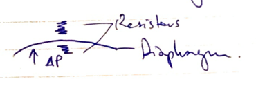
- Consists of a diaphragm & a strain gauge
- Converts pressure waveform into electrical signal
Flush system
- Pressurised saline @300mmHg
- Allows slow infusion @ 2mL/hr to maintain patency
Signal processor cable
- Electrical signal from transducer is transmitted for filtering, amplification, analysis & display on screen as Pressure v Time wave
Mechanism of Action
Transducer = device that converts E. from one form to another
Strain Gauge = sensor whose electrical resistance varies with applied force
- Used to measure ∆pressure
- Arterial pulsation moves saline column back & forth
- Hydraulic Coupling causes diaphragm to move
- Flexible diaphragm attached to strain gauges
- All 4 strain gauges connected electrically to form Wheatstone Bridge circuit
3 resistors = known value
1 resistor = unknown (variable)
- Resistors are arranged so when R1/R2 = R3/Rx there is NO FLOW (null deflection)
The VG Galvanometer measures current flow between D & B
If the bridge is balanced, there is no flow
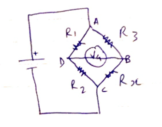
When diaphragm alters resistance in strain gauge, one gets stretched the other gets compressed (on the other side of the diaphragm)
Increased resistance is measured as change in current flow
Electrical signal transmitted via cable to microprosessor
Displayed as P v T wave
Static & Dynamic Calibration
Static calibration = ability to record stationary event
- Requires zeroing
- Zero reference point is the air-fluid interface above/below diaphragm when tap open to air
- Zero reference pt & cannula tip need to be the same level → ∴each time patient is moved the transducer height should be moved/system re-zeroed
Dynamic calibration = reliably record rapidly changing events
Resonant frequency = the frequency at which the system oscillates when disturbed
→ The NF of the IABP should be much higher than the primary of the waveform
→ Otherwise the system will resonate excessively
→ Overestimate SBP, underestimate DBP
Damping = the absorption of the Energy of oscillations which will ↓ their amplitude
→ Damping caused by
- Friction in fluid pathway
- Vasospasm
- 3-way taps
- Narrow, long, compliant tubing
- Kinks in cannula/tubing
Information Derived from the Trace
- (Blood Pressure)
- Pulse rate
- Pulse rhythm
- Wave morphology
- Pulse Pressure Variation
- SV = Area Under Curve (from systolic upstroke to Diacrotic Notch)
- Slope of upstroke gives indication of Contractility
- Position of diacrotic notch reflects SVR
- Dynamic Calibration information (resonance & damping)
- Author: Krisoula Zahariou